
This page aims to be a guideline for students interested in building their own 8051 based prototyping environment. This 80’s microcontroller is still used nowadays, and it is a great teaching tool. In the Electrical and Electronics Engineering (EEL) courses at UFSC it is used in the first part of the Microprocessors module. It is the entry architecture, and in the second part of the module the students are exposed to the ARM architecture. There are several tutorials available on the Web, and the guideline next was prepared targeting the EEL students’ needs.
List of items needed to build a minimum 8051 setup:
- AT89S52 (8051 microcontroller)
- Resistors: 1 x 10kΩ; 1 x 220Ω
- Capacitors: 2 x 22 pF; 1 x 10 uF
- 1 crystal 11.0859 MHz
- 1 LED
- Breadboard (or protoboard)
- Wires for the connections
- An 8051 programmer (in this guideline an Arduino is used as an 8051 programmer)
Pieces of software and configuration files:
- Sketch to turn the Arduino board into an ISP programer (to write the 8051 program to the AT89S52 flash program memory): ArduinoISP.ino.
- Software to send the 8051 .hex file from a host computer to the Arduino board: Avrdude
- Configuration file used by Avrdude in order to identify the AT89S52 device: configuration file
- 8051 .hex example file: blink.hex
In Figure 1 there is a block diagram of the proposed 8051 prototyping setup, where R3, R4, R5, R6 and the respective LEDs are optional. The LED next to R3 is used just to indicate that the 8051 is powered on. The R4, R5, and R6 LEDs are used in order to debug eventual problems in the Arduino during 8051 programing.
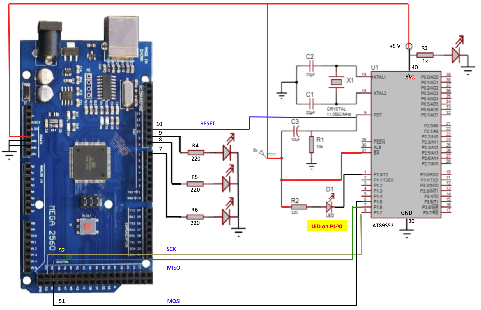
Figure 1. 8051 prototyping setup using an Arduino as a programmer.
STEP 1 – Find the components
- Mouser and Digi-key are good options, but the “Brazilian” costs might be a bit high,
- At the time this guideline was written, the AT89S52 device was bought on Mercado Livre, from a company called FJMSoft from São José, SC.
- The breadboard and Arduino are available also on Mercado Livre, or Filipeflop.
- The remaining components (resistors, capacitors, …) have been “cannibalized” from old boards.
- VERY IMPORTANT!! This guideline can be used with several 8051 based components, but it has been tested only with AT89S52. It is important to pay attention also to the ‘S’ in the device’s name. For instance, for the AT89C52 this guideline does not apply, as only the ‘S’ devices can be programmed through the ISP protocol (using the Arduino solution).
STEP 2 – Connect the components
- Place the AT89S52 device on the breadboard, and connect all the components as shown in Figure 1.
- Some pictures and a video showing the assembly steps will be provided soon.
STEP 3 – Setting up Arduino as an 8051 programer
- This step can be skipped, in case you have a proper programmer for the 8051 as, for instance, this one.
- However, in case you own an Arduino board, it can be used as a programmer for the 8051:
- In the Arduino IDE, open: File -> Examples -> 11.ArduinoISP -> ArduinoISP.
- This sketch needs a couple of modifications in order to be adapted to the AT89S52 and, to avoid typo mistakes, just use this one instead which has already been modified: ArduinoISP.ino.
- Download the ArduinoISP.ino to the Arduino board.
STEP 4 – Writing the 8051 .hex file to the AT89S52
- The .hex file can be generated using Keil, sdcc, or any other compiler/assembler tool for the 8051 family.
- Avrdude can be used to write the .hex file to the 8051 program memory:
- Download Avrdude and install it on your computer.
- Copy the target 8051 file (the .hex file) and Avrdude’s configuration file to a folder of your choice.
- Open a terminal, and type the following command: avrdude -p at89s52 -b 19200 -C avrdude-at89s52.conf -c avrisp -P /dev/cu.usbmodem14101 -U flash:w:blinkled.hex
- where:
- at89s52 is the part number, found in avrdude-at89s52.conf
- 19200 is communication bit rate, defined in ArduinoISP.ino
- avrdude-at89s52.conf is the configuration file for the AT89S52 device
- avrisp is the programmer type, defined in avrdude-at89s52.conf
- /dev/cu.usbmodem14101 is the serial port where the Arduino board is connected to. In this example, this is the serial port used over USB in a Mac notebook.
- blinkled.hex is the name of the .hex file that is going to be written to the AT89S52 flash memory.
STEP 5 – TBC